TechInsights:首探英飞凌业界首款400V SiC MOSFET
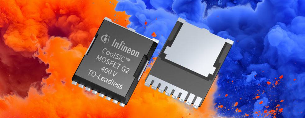
TechInsights近日获得来自英飞凌的业界首款400V碳化硅(SiC)MOSFET:型号IMBG40R015M2H(400V、15mΩ CoolSiC G2 MOSFET),并进行初步的探索性分析。
以下为分析报告全文:
A First Look at Infineon’s and Industry’s First 400 V SiC MOSFET
抢先了解 Infineon 和业界首款 400 V SiC MOSFET
TechInsights is excited to announce that we have Infineon’s, and the industry’s, first 400 V silicon carbide (SiC) MOSFET in-house. The IMBG40R015M2H 400 V, 15 mΩ CoolSiC G2 MOSFET [1] was brought in in early September, and the initial exploratory analysis has completed.
TechInsights 很高兴地宣布,我们拥有英飞凌和业界首款 400 V 碳化硅 (SiC) MOSFET。IMBG40R015M2H 400 V、15 mΩ CoolSiC G2 MOSFET [1] 于 9 月初推出,初步探索性分析已完成。
Infineon is among the industry leaders in the semiconductor market. For the 2023 fiscal year, Infineon claimed the number 1 market share in power discrete and modules with a 20.6% figure [2]. This is also qualitatively supported in TechInsights’ Power Semiconductor Market Share 2023 Report (PWS-2407-801), where we show that Infineon leads the power semiconductor market from 2020-2023 consecutively.
Infineon 是半导体市场的行业领导者之一。2023 财年,英飞凌以 20.6% 的份额在功率分立器件和模块领域占据第一 [2]。TechInsights 的 2023 年功率半导体市场份额报告 (PWS-2407-801) 也对此提供了定性支持,其中我们表明英飞凌在 2020-2023 年连续引领功率半导体市场。
To quickly rehash the SiC technology history once again, it took decades of academic research for SiC FET technology to reach first commercialization of a 1200 V JFET by now-closed SemiSouth in 2008, followed by the first 1200 V MOSFET by Cree, now Wolfspeed. The introduction of SiC MOSFETs demonstrated that the interfacial issues between the gate dielectric and the SiC material can practically be addressed. Since then, manufacturers have continually improved their device performance figures. By 2017, both Infineon and Rohm released the market’s first SiC trench MOSFETs. Furthermore, by 2024, Rohm has released its fourth-generation trench SiC MOSFET, and Infineon has released its second-generation trench SiC MOSFETs, both with significant device performance improvements over the previous generations.
为了再次快速回顾 SiC 技术的历史,SiC FET 技术经过数十年的学术研究,才在 2008 年由现已关闭的 SemiSouth 首次实现 1200 V JFET 的商业化,随后是 Cree(现为 Wolfspeed)的第一个 1200 V MOSFET。SiC MOSFET 的引入表明,栅极电介质和 SiC 材料之间的界面问题实际上可以得到解决。从那时起,制造商不断改进其设备性能数据。到 2017 年,Infineon 和 Rohm 都发布了市场上第一款 SiC 沟槽式 MOSFET。此外,到 2024 年,Rohm 已推出第四代沟槽式 SiC MOSFET,英飞凌已推出第二代沟槽式 SiC MOSFET,这两款产品均比前几代产品具有显著的器件性能提升。
Conventionally, 650 V has long been considered the practical lower limit of SiC devices with the relative cost outweighing the benefits for lower voltages. That is, until now. Voltage range below 650 V was where silicon (Si) and gallium nitride (GaN) have been the intuitive go-to for designers in terms of device selection. For this reason, Infineon’s announcement for its 400 V SiC MOSFET has garnered industrial excitement and interest. The 400 V SiC MOSFET is based on Infineon’s second generation (G2) CoolSiC technology. TechInsights released a blog on the first impression of this technology, as well as an in-depth process analysis report (PEF-2402-801) and full process flow analysis report (PFF-2404-801) on the 1200 V, 7.7 mΩ (typical) IMBG120R008M2H device.
传统上,650 V 一直被认为是 SiC 器件的实际下限,其相对成本超过了较低电压的好处。也就是说,直到现在。在器件选择方面,低于 650 V 的电压范围是硅 (Si) 和氮化镓 (GaN) 的直观选择。因此,英飞凌宣布推出其 400 V SiC MOSFET 引起了业界的兴奋和兴趣。400 V SiC MOSFET 基于英飞凌的第二代 (G2) CoolSiC 技术。TechInsights 发布了一篇关于这项技术第一印象的博客,以及关于 1200 V、7.7 mΩ(典型值)IMBG120R008M2H器件的深入工艺分析报告 (PEF-2402-801) 和完整工艺流程分析报告 (PFF-2404-801)。
The remainder of this blog will show the results of TechInsights’ initial analysis of the IMBG40R015M2H 400 V SiC MOSFET as well as provide commentary in the device and application contexts.
本文接下来将展示 TechInsights 对 IMBG40R015M2H 400 V SiC MOSFET 的初步分析结果,并在器件和应用环境中提供评论。
TechInsights’ First Look at the IMBG40R015M2H 400 V CoolSiC G2 MOSFET
TechInsights 对 IMBG40R015M2H 400 V CoolSiC G2 MOSFET 的初探
The IMBG40R015M2H 400 V CoolSiC G2 MOSFET comes in a 7-lead TO-263 package measuring nominally 10.2 mm × 10.0 mm × 4.41 mm without leads. The package comprises a single SiC MOSFET die with the drain terminal attached to the die paddle portion of the lead frame, functioning as an external drain tab, and gate, source driver, and power source package leads are connected to the die with aluminum bond wires. The top and bottom package photographs are shown in Figure 1.
IMBG40R015M2H 400 V CoolSiC G2 MOSFET 采用 7 引脚 TO-263 封装,标称尺寸为 10.2 mm × 10.0 mm × 4.41 mm,无引脚。该封装包括一个 SiC MOSFET 芯片,其漏极连接到引线框架的芯片桨部分,用作外部漏极片,栅极、源极驱动器和电源封装引线通过铝键合线连接到芯片。顶部和底部封装照片如图 1 所示。

Figure 1: top (left) and bottom (right) package photographs of the IMBG40R015M2H 400 V SiC MOSFET component.
图 1:IMBG40R015M2H 400 V SiC MOSFET 元件的顶部(左)和底部(右)封装照片。
Figure 2 is a side-view package X-ray Image of the IMBG40R015M2H component. The use of Infineon’s .XT package interconnect technology [3] is evident in the minimal die-to-die paddle spacing observed in the package X-ray image. The .XT package interconnect technology replaces conventional die attach with a diffusion-based process, resulting in an ultra-thin die attach layer to offer thermal resistance improvements. This can benefit SiC MOSFETs in two ways: since SiC MOSFETs allow a higher power density than their Si counterparts, this also translates to the potential for a higher thermal concentration during operations. Improving the thermal management at the package level will be beneficial. In addition, the Young’s modulus of 4H SiC, the industry standard polytype used in SiC power devices, is about 3.1 times of that of Si’s [4]. This means a SiC MOSFET can have an elevated risk of stress and strain related delamination. The .XT technology claimed to address this compared to conventional die attach techniques to improve package reliability as well [5].
图 2 是 IMBG40R015M2H 组件的侧视图包装 X 射线图像。使用英飞凌的 .XT 封装互连技术 [3] 在封装 X 射线图像中观察到的最小晶粒间距中显而易见。这。XT 封装互连技术用基于扩散的工艺取代了传统的芯片贴装,从而形成超薄的芯片贴装层,从而提高了热阻。这可以通过两种方式使 SiC MOSFET 受益:由于 SiC MOSFET 允许比 Si MOSFET 更高的功率密度,这也意味着在运行过程中可能会产生更高的热浓度。改进封装级别的热管理将是有益的。此外,4H SiC 的杨氏模量(SiC 功率器件中使用的行业标准多型)约为 Si 的 3.1 倍 [4]。这意味着 SiC MOSFET 可能具有更高的应力和应变相关分层风险。这。与传统的芯片贴装技术相比,XT 技术声称可以解决这个问题,从而提高封装的可靠性 [5]。

Figure 2: side view X-ray of the IMBG40R015M2H 400 V SiC MOSFET package.
图 2:IMBG40R015M2H 400 V SiC MOSFET 封装的侧视图 X 光。
Figure 3 shows the 400 V SiC MOSFET die extracted by TechInsights. From the measured die dimensions, specific-RDS(ON) figure normalized to the die area (RDS(ON)·Adie) was calculated. Compared to other SiC FETs analyzed at TechInsights, the RDS(ON)·Adie figure is about half or less of most 600-750 V MOSFETs, and comparable to the UnitedSiC (Qorvo) UJ4C075018K4S 750 V JFET, a device presented the our in-depth process report PEF-2101-801. Compared to SiC MOSFETs, SiC JFETs can inherently have a lower RDS(ON) since the gate oxide interface and channel challenges in MOSFETs are bypassed and the channel resistance component is removed from the overall RDS(ON).
图 3 显示了 TechInsights 提取的 400 V SiC MOSFET 芯片。根据测得的芯片尺寸,将特定 RDS(ON) 值归一化为芯片面积 (RDS(ON)·Adie) 被计算出来。与 TechInsights 分析的其他 SiC FET 相比,RDS(ON)·Adie 数字大约是大多数 600-750 V MOSFET 的一半或更少,与 UnitedSiC (Qorvo) UJ4C075018K4S 750 V JFET 相当,我们的深入工艺报告 PEF-2101-801 介绍了该器件。与 SiC MOSFET 相比,SiC JFET 本身具有更低的 RDS(ON),因为 MOSFET 中的栅极氧化层界面和通道挑战被绕过,并且通道电阻分量从整体 RDS(ON) 中去除。

Figure 3: IMBG40R015M2H 400 V SiC MOSFET die photograph.
图 3:IMBG40R015M2H 400 V SiC MOSFET 芯片照片。
Figure 4 shows a selected corner of the die. Initial analysis indicates a trench gate pitch of that is about a ~7% reduction from the trench gate pitch observed in the 1200 V IMBG120R008M2H previously analyzed at TechInsights (PEF-2402-801). Other sources of performance improvement, such as the MOSFET structures and substrate thickness, are yet to uncovered. TechInsights plans on performing additional analysis on the 400 V SiC MOSFET die, and the trench gate pitch measurement may further be improved in the process.
图 4 显示了芯片的选定角。初步分析表明,与之前在 TechInsights (PEF-2402-801) 分析的 1200 V IMBG120R008M2H中观察到的沟槽栅间距相比,该沟槽栅极间距减少了约 ~7%。性能改进的其他来源,例如 MOSFET 结构和衬底厚度,尚未被发现。TechInsights 计划对 400 V SiC MOSFET 芯片进行额外分析,在此过程中可能会进一步改进沟槽栅极间距测量。

Figure 4: IMBG40R015M2H 400 V SiC MOSFET die corner photograph.
图 4:IMBG40R015M2H 400 V SiC MOSFET 芯片边角照片。
Putting the IMBG40R015M2H 400 V SiC MOSFET in Context
将 IMBG40R015M2H 400 V SiC MOSFET 置于上下文中
Table 1 is a summary of selected device parameters and calculated figures-of-merit (FOMs) based on the datasheets for the 400 V IMBG40R015M2H [1] and the 650 V IMBG65R015M2H [6] CoolSiC G2 MOSFETs. The IMBG65R015M2H was selected as a 650 V example device which also uses a 7-lead TO-263 package with a comparable 14.5 mΩ typical RDS(ON).
表 1 是根据 400 V IMBG40R015M2H [1] 和 650 V IMBG65R015M2H [6] CoolSiC G2 MOSFET 的数据表总结了所选器件参数和计算的品质因数 (FOM)。该IMBG65R015M2H被选为 650 V 示例器件,该器件也使用 7 引脚 TO-263 封装,具有类似的 14.5 mΩ 典型 RDS(ON)。
An inspection of Table 1 indicates that while the selected 400 V and 650 V SiC MOSFETs have comparable RDS(ON), the QGD, QOSS, EOSS, and QG values, and the related FOMs all favor the 400 V device. This indicates that to achieve the 14.5 mΩ RDS(ON) for the 650 V IMBG65R015M2H device, the die size was scaled up, leading to higher gate charge and energy loss figures. At the same time, stepping the voltage rating down to 400 V allowed design room for device and die structure optimization to fine tune these device parameters.
对表 1 的检查表明,虽然所选的 400 V 和 650 V SiC MOSFET 具有相当的 RDS(ON),但 QGD、QOSS、EOSS 和 QG 值以及相关的 FOM 都有利于 400 V 器件。这表明,为了在 650 V IMBG65R015M2H器件上实现 14.5 mΩ RDS(ON),芯片尺寸被放大,从而导致更高的栅极电荷和能量损耗数字。同时,将额定电压降至 400 V,为器件和芯片结构优化提供了设计空间,以微调这些器件参数。
It may be worth noting that Infineon has also released a 400 V IGT40R070D1 CoolGaN device, also considered as a specialized voltage rating for GaN technologies. However, Infineon had stated that the 400 V SiC MOSFET is still the overall winner in designs requiring the maximum efficiency.
值得注意的是,英飞凌还发布了一款 400 V IGT40R070D1 CoolGaN 器件,该器件也被认为是 GaN 技术的专用额定电压。然而,英飞凌曾表示,400 V SiC MOSFET 仍然是需要最高效率的设计的总赢家。

Table 1: Selected device parameters and figures-of-merits from Infineon IMBG40R015M2H 400 V and IMBG65R015M2H 650 V CoolSiC G2 MOSFETs.
表 1:Infineon IMBG40R015M2H 400 V 和 IMBG65R015M2H 650 V CoolSiC G2 MOSFET 的选定器件参数和品质因数。
What this means in terms of applications is that in topologies where the higher voltage rating is not required, the 400 V SiC MOFET can offer better power density, switch performance, and efficiency. Such applications can include server power supplies (PSUs), inverter motor control, power supplies, as well as solar and energy stage systems. Infineon’s publication indicates the development of the 400 V SiC MOSFET was motivated by specific customer requirements and provides improved switching and conduction losses compared to the 650 V SiC MOSFETs, yielding an efficiency improvement of up to 0.3% and a flatter RDS(ON) versus temperature curve. This difference can translate to significant power difference in high-power applications, such as server power supplies (PSUs). It was stated that using the 400 V Si MOSFETs in a multi-level power factor correction (PFC), the AC/DC stage of a server PSU can reach a power density of >100 W/in³ and an efficiency of 99.5%.
就应用而言,这意味着在不需要更高额定电压的拓扑中,400 V SiC MOFET 可以提供更好的功率密度、开关性能和效率。此类应用包括服务器电源 (PSU)、逆变器电机控制、电源以及太阳能和能源舞台系统。英飞凌的出版物表明,400 V SiC MOSFET 的开发是出于特定的客户要求,与 650 V SiC MOSFET 相比,它提供了更好的开关和导通损耗,效率提高了 0.3%,RDS(ON) 与温度曲线更加平坦。这种差异可以转化为高功率应用(如服务器电源 (PSU))中的巨大功率差异。据称,在多级功率因数校正 (PFC) 中使用 400 V Si MOSFET,服务器 PSU 的 AC/DC 级可以达到 >100 W/in³ 的功率密度和 99.5% 的效率。
Learn more
Power semiconductor devices are essential in all electronics applications, including ever-growing markets like AI, datacenters, automotive, electric vehicles, as well as industrial and consumer electronics.
了解更多
功率半导体器件在所有电子应用中都是必不可少的,包括 AI、数据中心、汽车、电动汽车以及工业和消费电子产品等不断增长的市场。

 成员
成员 - 成交数 --
- 成交额 --
- 应答率